


Send Message
Privacy statement: Your privacy is very important to Us. Our company promises not to disclose your personal information to any external company with out your explicit permission.

EN
 October 27, 2020
Emergency lighting is a very important lighting device. It automatically charges the backup battery during normal power supply, automatically switches battery power after power failure, provides emergency lighting function, and is crowded in high-rise buildings, teaching buildings, shopping malls and entertainment venues. The place is widely used. Because it involves the safety evacuation of personnel in the building fire, fire emergency lighting and direction instructions, it plays a very important role in fire rescue, even known as the "light of life." LED is used as emergency light for emergency lighting. It has long life, low energy consumption, high color rendering, easy maintenance, small size, fast lighting speed, no stroboscopic light, and luminous efficiency is much higher than traditional light source, no harmful metal mercury. It is very environmentally friendly and has become a mainstream product. The design of LED emergency lighting is based on the premise of the national standard of fire emergency lighting (GB17945-2000), mainly from the realization of functions, main technical indicators, emergency lighting circuit design, normal lighting and charging control circuit design and automatic emergency Comprehensive design of conversion circuit design and other aspects.
1 Main functions of emergency lighting
The main functions of LED emergency lighting are as follows:
(1) Automatic switching function. When the power failure occurs, the built-in control circuit automatically switches the power supply within 5 seconds (within 0.25s in the high-risk area) and enters the emergency state. When the utility power resumes power supply, it automatically switches back to the charging state.
(2) Constant current charging function. When charging, the red and green indicators are on. When full, the red indicator light is off. At this time, the trickle charge state is turned; the green indicator light shows the main power state, and the mains power is normally turned on.
(3) Fault detection function. If the battery fuse is broken or the contact is poor, or the internal control circuit is abnormal, the built-in self-test circuit will automatically light up the yellow indicator.
(4) Over-discharge protection function. When the battery voltage is discharged to 80% of the rated voltage, the electronic switch immediately cuts off the discharge circuit to ensure the long life of the battery.
(5) Test button function. Under the condition that the main power is normally supplied, pressing the test button is equivalent to cutting off the external power supply for simulating the power failure state test. The emergency light can be turned off by pressing the button under the condition of main power failure.
2 Main technical indicators of emergency lighting:
According to the national standard (GB17945-2000), the main technical indicators that LED emergency lighting should reach.
(1) The emergency working time of the fire emergency luminaire shall be not less than 90min, and not less than the nominal emergency working time of the luminaire itself.
(2) Fire emergency luminaries shall be provided with main power, charging and fault status indicators. The main power state is green, the charging state is red, and the fault state is yellow. Centralized power-type fire emergency luminaries shall be provided with main power and emergency power status indicators, the main power status is green, and the emergency status is red. The fire emergency luminaire that shares the power supply line between the main power and the emergency power supply can use only the red indicator light.
(3) Fire emergency lighting should have over-charge protection and short circuit protection of charging circuit. The charging time of the fire emergency light should be no more than 24h, and the maximum continuous overcharge current should not exceed 0.05C5A (1C means battery capacity current, 0.05C is 0.05 times battery capacity current; C5 means 5 hours capacity discharge time). The maximum charging current of a centralized power-type fire emergency luminaire when using a maintenance-free lead-acid battery should not exceed 0.4 C20A.
(4) Fire emergency luminaires should have over-discharge protection. The battery discharge termination voltage should not be less than 80% of the rated voltage. After the discharge is terminated, the fire emergency light should not be restarted even if the battery voltage is restored without recharging, and the static bleeder current should be no more than 10-5 C5A. . The maximum discharge current of a centralized power-type fire emergency luminaire when using a maintenance-free lead-acid battery should not exceed 0.6 C20A. The battery discharge termination voltage should not be less than 90% of the rated voltage of the battery, and the static bleeder current should be no more than 10-5 C20A.
(5) The fire emergency luminaire should not be transferred to the emergency state within the range of 187~242V.
(6) The main electric voltage when the fire emergency luminaire is transferred from the main electric state to the emergency state shall be in the range of 132 to 187V. The mains voltage when returning from the emergency state to the main power state shall be not less than 187V.
(7) The insulation resistance between the main power input terminal and the casing of the fire emergency luminaire shall be not less than 50 MΩ, and the insulation resistance between the external live terminal and the casing with insulation requirements shall be not less than 20 MΩ.
(8) The main power input end of the fire emergency luminaire and the casing shall withstand a frequency of 50 Hz ± 1%, a voltage of 1500 V ± 10%, and a test of 60 s ± 5 s. The external live terminal of the fire emergency luminaire (rated voltage ≤ 50VDC) and the housing shall withstand a frequency of 50 Hz ± 1%, a voltage of 500V ± 10%, and a test lasting 60s ± 5s. During the test, the fire emergency luminaire shall not have surface arcing and breakdown. After the test, the fire emergency luminaire shall be able to work normally.
3 LED volt-ampere characteristics and power requirements:
According to the color of the light, the LED can be divided into blue light (InGaN) 470nm, green light Green (GaP: N) 550 nm, yellow light (GaP: N - N) 587 nm, red light Red (InGaAlP) 617nm, super Red-light Super-Red (InGaAlP) 630nm, white LED and other products. Due to the differences in their inherent characteristics, different power supplies need to be designed for their applications.
3.1 Volt-ampere characteristics of standard red, green and yellow LEDs For a standard red, green and yellow LED with a diameter of 5 mm, the curve of forward voltage (VF) and forward current (IF) is shown in the figure. 1 is shown. As can be seen from Figure 1, the standard red, green, and yellow LEDs have a forward voltage of 1.4 to 2.6V, and the forward voltage drop increases as the forward current increases. When the forward current is less than 10 mA, the forward conduction voltage changes only a few hundred millivolts.
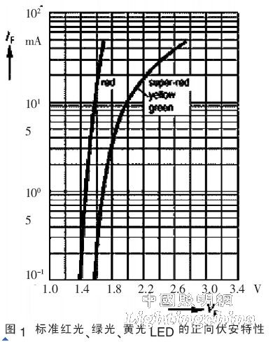
The easiest way to use an LED is to apply a voltage source to a loop that is connected in series with the LED. As long as the operating voltage remains constant, the LED can emit a constant intensity of light (although the intensity decreases as the ambient temperature increases) By changing the resistance of the series resistor, the light intensity can be adjusted to the required intensity. For example, with a 5V power supply, a green LED with a forward operating current of 10mA should have a constant operating voltage of 2V, then the series resistor is R=(5 -VF)/10mA = 300Ω.
3.2 Volt-ampere characteristics of blue and white LEDs
The display wavelength (color) of a blue (InGaN) LED changes with the forward current, as shown in Figure 2. The forward volt-ampere characteristics of blue LEDs are one of the many curves in Figure 3.

When the operating current is in the range of 4 to 10 mA, the forward current / voltage change rate is ΔI / ΔV = 2.6 mA / 0.1V;
When the operating current is above 10 mA, the forward current/voltage change rate is ΔI / ΔV = 3.3 mA / 0.1V. LEDs that actually emit white light do not exist because LEDs are characterized by emitting only one wavelength of light. For this reason, in the white LED design, a blue light-emitting InGaN base material is used to cover the conversion material, which emits yellow light when excited by blue light, thus obtaining a mixture of blue light and yellow light, which is visible to the naked eye. White. The current-voltage curve for a randomly selected white LED is shown in Figure 3.
As can be seen from Figure 3, the white LED requires a voltage drive higher than 3V. When the forward current is 10mA, the forward voltage ranges from 3.5 to 3.8V. Directly driving a white LED with a battery is difficult because the vast majority of the battery will turn off as the discharge causes the voltage to be lower than the minimum forward voltage required by the LED. The lithium battery can provide 4.2V output voltage when fully charged, and will drop to the nominal 3.5V voltage in a short period of working time. As the battery is discharged, its output voltage will further drop to 3.0V, which can directly meet the requirements. Drive power LED lighting requirements.

For these white LEDs, applying a voltage of 3.3V (right dotted line in Figure 3) produces a forward current of 2 to 5 mA, resulting in white light of different brightness. Many portable or battery-powered devices use white LEDs as backlights. For example, PDA color displays require a white background light to restore color to the original. In applications where high white light illumination is required, the illumination brightness of a single white LED is not sufficient. It is necessary to illuminate several white LEDs at the same time, but a specific power supply must be used to ensure that their intensity and color are consistent even in the battery. This should also be the case for discharge or other conditions, so a charge pump with current control is typically used as the power supply for the white LED, which provides a sufficiently high output voltage and loads the same current on the LEDs connected in parallel. For example, Maxim offers a charge pump with current control (using the MAX1912 chip) that can simultaneously drive more than three white LEDs in parallel with an output current of up to 60mA.
4 LED emergency lighting control circuit design:
4.1 Transformer, rectification and filter circuit design is normally powered by AC220V mains under normal conditions. For this purpose, a transformer, rectifier and filter circuit is designed, as shown in Figure 4. Its function is: AC220V is stepped down to AC8V voltage by transformer T1, and after DC1~D4 bridge rectification and C1 filtering, DC voltage is obtained, which is used for charging circuit and other circuits.

4.2 Status indication circuit design The emergency lighting mainly has three working states: main power supply state, charging working state and circuit fault state. It is indicated by standard green LED, red LED and yellow LED respectively, designed according to control requirements. The main power indication, the charging indication, the fault indication circuit and the working state detection circuit are shown in FIG. 5.
(1) Main power supply status. After the main power supply is turned on, the DC voltage obtained by step-down, rectification, and filtering is limited by R1, Rx, and D10, so that the main power indicator D10 (green) is on, and the D10 forward conduction voltage is 2V. The normal display current is 10~20mA; after the main power is cut off, the main power indicator D10 is off.
(2) Charging working status. At the beginning of charging, the charging battery voltage is low, Q4 is cut off, and the rectified and filtered DC voltage is limited by R1, R9, and D11, so that the charging indicator D11 (red) is on, and the D11 forward conduction voltage is 1.8V. The normal display current is 10~20mA; when the battery voltage rises to a certain value, D7 is cut off, and through the R8→R10→Q4(9013) path, Q4 is turned on, so that the red light D11 is extinguished.

(3) Circuit failure status. In the case of mains power supply, when the battery fails or the fuse connected in series is blown, the applied DC voltage is higher than 6.8V to make the voltage regulator D9 work, and then the R12 makes the fault light D12 (yellow) bright, D12 positive The conduction voltage is 2V, and the normal display current is 10 to 20mA. When the main power is cut off, the fault light D12 goes out.
4.3 Emergency conversion circuit design When the main power supply is normal, the rectified and filtered DC voltage is limited by R8 and D7 to charge the battery BT. At the same time, the true current voltage is charged by R1 and R3 to C2 for emergency conversion. Be prepared and turn Q1 on, but D5 and Q2 are cut off because the potential at point C is higher than the potential at point A.
When the main power is turned from the power supply to the power off, the charging voltage on C2 keeps Q1 on, and the C point changes from high to low, turning D5 and Q2 on, and the rechargeable battery supplies power to the LED emergency lighting circuit. Select the battery capacity to be 3.6V/300mAh. When the LED lighting circuit current is less than or equal to 200mA, ensure that the LED emergency lighting working time is not less than 90min. In the case that the main power is normally supplied, the test button SB is closed, the main power is cut off and the emergency lighting state is entered, and the test button is turned on to restore the main power supply state.

According to the above control requirements, the emergency conversion circuit of the emergency lighting designed is shown in Figure 6.

4.4 LED emergency lighting circuit The emergency lighting function of the emergency lighting is realized by white LED. Because the brightness of single white LED is limited, many LEDs can not be used to meet the actual requirements. The designed control circuit is shown in Figure 7. Show. In order to illuminate the uniformity of the light, the emergency lighting circuit is made into two boards, which are distributed on both sides of the base. Each white light LED is installed on each emergency lighting board. The forward voltage of each LED is about 3V. The operating current range is 10 to 30 mA. At the same time, in order to avoid the problem of unbalanced power consumption caused by the discrete voltage of the LED forward voltage, each LED is connected in series with one resistor and then used in parallel. In this design, a total of 8 white LED circuits are used. The total working current cannot exceed 200mA, that is, the operating current of each LED circuit should not exceed 25mA to ensure the emergency working time is not less than 90min.
5 Conclusion:
With the continuous development of LED technology and the decline of cost, LED will play an increasingly important role in emergency lighting and daily life. When developing and designing the control circuit of emergency lighting, it is necessary to fully consider the electro-optic characteristics of various spectral LEDs according to the relevant national standards, and complete the design of LED driving circuit from the perspective of high efficiency and high reliability, which is to ensure the wide application of LED. basis.
references:
[1] SAUERLANDER G, HENTE D, RADERMACHER H, et al. Driver electronics for LEDs [C]//IndustryApplications Conference, 2006.41st IAS Annual Meeting. Tampa: IEEE, 2006:2621-2626 .
[2] Lu Qiusheng. LED Lighting and Application [J]. Lights and Lighting, 2009, 33(4): 24-28.
[3] Yan Xiaofeng, Zhang Qi. Technical Discussion of White LED Driver[J]. Journal of Anyang Institute of Technology, 2009(4): 6-9.
[4] Bai Lin, Liang Hongbao. Design and Driving Technology of High Power White LED Street Light Panel[J]. Journal of Luminescence, 2009, 30(4): 487-493.
Edit: Sophy
The above is the LED emergency lighting driver circuit design we have listed for you. You can submit the following form to obtain more industry information we provide for you.
You can visit our website or contact us, and we will provide the latest consultation and solutions
Send Inquiry
Most Popular
lastest New
Send Inquiry
Related Products List
Contact Us

Privacy statement: Your privacy is very important to Us. Our company promises not to disclose your personal information to any external company with out your explicit permission.
Fill in more information so that we can get in touch with you faster
Privacy statement: Your privacy is very important to Us. Our company promises not to disclose your personal information to any external company with out your explicit permission.